The single-phase motor stator has a laminated iron core with two windings arranged perpendicularly. In this paper their values are considered to be 093 095 and 0038 respectively 12.

Single Phase Induction Motor Working Construction Applications The Engineering Knowledge
Basic Design and Theory of Operation The alternating current AC induction motor is one of the most rugged and most widely used machines in industry.

. An induction motor can therefore be made without electrical connections to the rotor. Karnavaseeduthgr requirements based mainly on the classic output coefficient concept. Speed and Direction of Rotation 3.
Calculate number of stator turns per phase depending on previous B D L supply voltage math and assumed flux density shape factor i. Then numer- ous simulations over a larg e. Single Phase Induction Motor Double revolving field theory The three-phase induction motor starting torque inversely depends on the slip This implies that a small positive slip 001003 generates larger torque than a larger negative slip 195199 This torque difference drives the motor continues to rotate in a forward direction without any external torque.
B approach a sample single phase induction motor design is obtained regarding certain Kimmeria Xanthi 671 00 Greece. The single coil of a single-phase induction motor does not produce a rotating magnetic field but a pulsating field reaching maximum intensity at 0 and 180 electrical. The other is the auxiliary winding or starting winding.
An induction motor or asynchronous motor is an AC electric motor in which the electric current in the rotor needed to produce torque is obtained by electromagnetic induction from the magnetic field of the stator winding. A 14hp 110V 60Hz 2-pole single phase induction motor has a rotational loss of 10W at normal speeds. Let us use the following nomenclature.
If double layer winding is to be use then y should be divisible by 2. Up to 24 cash back 6Prepared by. Then numer- ous simulations over a large number of candidate motor topologies are conducted.
Application - The single-phase induction machine is the most frequently used motor for refrigerators washing machines clocks drills compressors pumps and etc. Select q13 to 10 and then find S1. This flux is known as the main flux.
Flux per pole in the air gap. Single-phase stator produces a nonrotating pulsating magnetic field. Of turns per phase.
Therefore a single-phase induction motor can to imagined to be consisting of two motors having a common stator winding but with their respective rotors revolving in opposite directions. Each rotor has resistance and reactance half the actual rotor values. One or 2 fans are attached to the shaft in the sides of rotor to cool the circuit.
1 are considered as the design variables of SPIM. The two equivalent circuits are connected in series. Induction Motor Design OUTPUT EQUATION We have to relate the output of the machine with its main dimensions.
QC 0 D 2Ln s 1 Where Q is output of IM in KVA Dis diameter of conventional IM L is length of core of circular IM n s is synchronous speed in RPS C 0 is output coefficient. The design parameters of linear induction motor are calculated from output equation. Operation Beyond the Range 0 s 1 7.
Once connected to the source the currents in three coils will be balanced and symmetrical The magnetic flux density generated by these currents stator at any arbitrary moment is given by The rotating magnetic field. Induction Motor Equivalent Circuit 5. Eph Induced EMF per phase in volts.
Three-phase induction motors are sometimes built with aluminum frames for general purpose applications below 55 kW Figure 15. The single-phase induction motor is the most frequently used motor for refrigerators washing machines clocks drills compressors pumps and so forth. The rotating magnetic field Consider a two-pole.
Slip ring Induction Motors 321 Squirrel cage Induction Motors a Stator Construction The induction motor stator resembles the stator of a revolving field three phase alternator. Approach a sample single phase induction motor design is obtained regarding certain requirements based mainly on the classic output coefficient concept. Form factor typically assumed.
X 6 x 7 and x 14 are often dictated by the motor- manufacturers. The Rotating Field 3. Now we assume that the rotor is rotating and it is placed in a magnetic field produced by the stator winding.
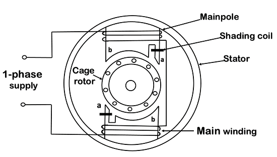
Most of single phase induction motors have Squirrel-Cage rotor. Run Capacitor Stator Winding Relay Rotary Switch Rotor Start capacitor Main or Run Windin. There are two major components of an AC induction motor.
Torque and Power Characteristics 6. Working of Single-phase Induction Motor Single-phase AC supply is given to the stator winding main winding. A typical contemporary single-phase induction motor with dual start and run capacitor in the auxiliary phase is shown in Figure 14.
One is the main and 2. Three phase induction motors are constructed into two major types. Squirrel cage rotor Wound Rotor In the wound rotor an insulated 3-phase winding similar to the stator winding wound for the same number of poles as stator is placed in the rotor slots.
Induced EMF per phase Applied Voltage per phase Iph Current per phase A. Initial values of these parameters are obtained from the conventional method of the SPIM design 12. An induction motors rotor can be either wound type or squirrel-cage.
The stationary or static component is. The equivalent circuit parameters are r1 13 Ohm r2 30 Ohm x1 25 Ohm x2 20 Ohm xc 50 Ohms Determine the line current line power factor power out and efficiency at. Several optimal design schemes of a single sided linear induction motor slim adopted in linear metro are presented in this paper firstly the equivalent circuit of slim fully considering the end effects half-filled slots back iron saturation and skin effect is proposed based on one dimensional air gap magnetic equations in the circuit.
Determination of Motor Constants 8. 1 4 1 Eph ph fw KV T K K f 1 1 E ph E K V Flux per pole Back EMF factor Turns per phase typically 085-095 higher for large power rating or small pole number 4 Fu. The 3-phase stator coils are placed 120o apart.
Squirrel cage Induction Motors 2. Another view is that the single-coil excited by a single-phase current produces two counter-rotating. The alternating current flowing through the stator winding produces magnetic flux.
Figure 15 Aluminum frame induction motor Source.
Types Of Single Phase Induction Motors Javatpoint
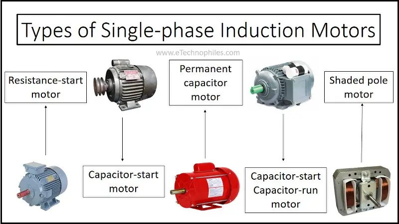
Types Of Single Phase Induction Motors And Their Applications

Types Of Single Phase Induction Motors Split Phase Capacitor Start Capacitor Run Electrical4u

Single Phase Induction Motor Working Construction Applications The Engineering Knowledge
Single Phase Motor Schematics And Working Electricaleasy Com

Types Of Single Phase Induction Motors Split Phase Capacitor Start Capacitor Run Electrical4u
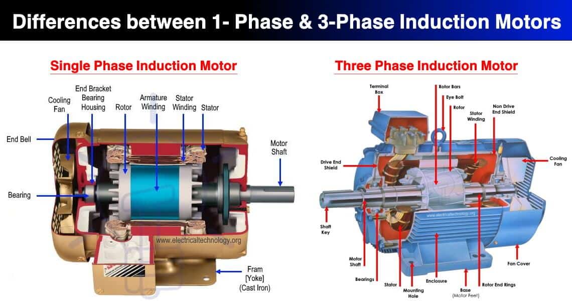
Difference Between Single Phase Three Phase Induction Motor

Single Phase Induction Motor Electrical4u
0 comments
Post a Comment